EV Basics L1 A
Basic Components of Electric Vehicles
Overview
Electric vehicles (EVs) represent a fundamental shift from internal combustion engines to electric propulsion systems. Understanding the key components and their interactions is essential for automotive engineers. This guide covers the ten primary systems that make EVs function effectively.
graph TD
    A[Battery] --> B[Motor]
    B --> C[Wheels]

    A --> D[12V Systems]
    E[Charger] --> A

    F[Control Unit] --> A
    F --> B
1. Battery Pack
Function: Primary energy storage system that powers the entire vehicle
Key Points
- Most EVs use lithium-ion battery technology due to high energy density
- Typically operates at 400V or 800V nominal voltage
- Measured in kilowatt-hours (kWh) - determines driving range
- Battery chemistry affects performance: NMC (Nickel Manganese Cobalt) for performance, LFP (Lithium Iron Phosphate) for cost-effectiveness
Engineering Considerations
- Energy density vs. power density trade-offs
- Cycle life (typically 1000-3000 charge cycles)
- Temperature sensitivity affects performance and lifespan
graph TD
    A[Battery Pack] --> B[High Energy Density]
    A --> C[High Voltage 400-800V]
    A --> D[Capacity kWh]

    B --> E[Lithium-ion Technology]
    E --> F[NMC Chemistry]
    E --> G[LFP Chemistry]

    F --> H[High Performance]
    G --> I[Cost Effective]
2. Battery Management System (BMS)
Function: Electronic "brain" that monitors and controls battery operation
Key Responsibilities
- Cell monitoring: Tracks voltage, current, and temperature of individual cells
- State estimation: Calculates State of Charge (SOC) and State of Health (SOH)
- Protection: Prevents overcharging, over-discharging, and thermal runaway
- Cell balancing: Ensures all cells charge/discharge evenly
Why It's Critical
Without proper BMS control, lithium-ion batteries can become dangerous or degrade rapidly. The BMS acts as a safety net and performance optimizer.
graph TD
    A[BMS] --> B[Monitor Cells]
    A --> C[Calculate SOC]
    A --> D[Balance Cells]
    A --> E[Safety Protection]
3. Motor Controller
Function: Electronic control unit that regulates electric motor operation
How It Works
- Receives commands from vehicle control unit (accelerator pedal position, desired torque)
- Controls motor speed and torque through precise electrical switching
- Implements control algorithms (typically Field Oriented Control for AC motors)
- Provides regenerative braking functionality
Key Features
- High-frequency switching (typically 10-20 kHz)
- Real-time feedback control using motor position sensors
- Safety interlocks and fault detection
graph TD
    A[Driver Input] --> B[Motor Controller]
    B --> C[Motor]
    C --> D[Feedback]
    D --> B
4. Electric Motor
Function: Converts electrical energy into mechanical motion to propel the vehicle
Common Types
- Permanent Magnet Synchronous Motor (PMSM): High efficiency, compact, uses rare earth magnets
- Induction Motor: Robust, no rare earth materials, slightly lower efficiency
- Switched Reluctance Motor: Simple construction, lower cost, higher noise
Key Characteristics
- High torque at zero RPM (instant torque delivery)
- Efficiency typically 90-95%
- Can operate as generator during regenerative braking
- Much simpler than internal combustion engines (few moving parts)
graph TD
    A[Motor Types] --> B[PMSM
95% Efficient]
    A --> C[Induction
90% Efficient]
    A --> D[Switched Reluctance
Low Cost]
5. EV Transmission
Function: Transfers power from motor to wheels, often with gear reduction
Types
- Single-speed reduction: Most common, typically 8:1 to 12:1 gear ratio
- Multi-speed: Some performance EVs use 2-speed for efficiency optimization
- Direct drive: Some designs eliminate transmission entirely
Why Different from ICE
Electric motors have wide speed ranges and don't need multiple gears like internal combustion engines. Most EVs use simple single-speed reductions.
block-beta
    columns 3

    A["Transmission Type"]:3

    B["Single-Speed"]:1
    C["Multi-Speed"]:1
    D["Direct Drive"]:1

    F["Gear Ratio"]:3

    G["8:1 to 12:1"]:1
    H["2-Speed Typical"]:1
    I["No Gears"]:1

    K["Usage"]:3

    L["Most Common"]:1
    M["Performance EVs"]:1
    N["Maximum Simplicity"]:1

    P["Key Features"]:3

    Q["Simple & Reliable"]:1
    R["Efficiency Optimization"]:1
    S["Motor Direct to Wheels"]:1

    style A fill:#409f00,color:#fff
    style F fill:#0a9ff7,color:#fff
    style K fill:#0f00e2,color:#fff
    style P fill:#00f0e2,color:#fff
6. Onboard & Offboard Chargers
Onboard Charger
Function: Converts AC power from electrical grid to DC power for battery charging
Specifications:
- Typical power levels: 3.3kW, 6.6kW, 11kW, 22kW
- Includes Power Factor Correction (PFC) for grid compatibility
- Built into the vehicle
Offboard Charger (DC Fast Charging)
Function: External high-power DC charging systems
Specifications:
- Power levels: 50kW to 350kW+
- Bypasses onboard charger, charges battery directly
- Enables rapid charging (20-80% in 15-45 minutes)
graph TD
    A[AC Grid] --> B[Onboard Charger
3-22kW]
    B --> C[Battery]

    D[DC Fast Charger
50-350kW] --> C
7. Inverter
Function: Converts DC power from battery to AC power for motor operation
Technical Details
- Uses power electronics (IGBTs or MOSFETs) for switching
- Creates three-phase AC waveforms from DC input
- Operates bidirectionally (motor mode and generator mode)
- Includes filtering to reduce electromagnetic interference
Integration
Often integrated with motor controller in a single unit called a "motor control unit" or "power electronics unit."
graph LR
    A[DC Battery] --> B[Inverter]
    B --> C[AC Motor]
    C --> B
    B --> A
8. DC-DC Voltage Converter
Function: Steps down high-voltage battery power to 12V for auxiliary systems
Why Needed
- Main battery operates at 400V or 800V
- Traditional automotive electronics (lights, radio, ECUs) operate at 12V
- Replaces the alternator found in conventional vehicles
Types
- Unidirectional: Battery to 12V system only
- Bidirectional: Can also charge main battery from 12V system (useful during vehicle startup)
graph TD
    A[High Voltage
400-800V] --> B[DC-DC
Converter]
    B --> C[12V Systems
Lights, Radio, ECUs]
9. Thermal Management System
Function: Controls temperature of critical EV components
Components Managed
- Battery cooling: Liquid cooling loops or air cooling to maintain 15-35°C
- Motor/inverter cooling: Prevents overheating during high-power operation
- Cabin heating/cooling: Heat pump systems for efficiency
System Types
- Air cooling: Simple, lower cost, limited effectiveness
- Liquid cooling: More effective, uses coolant loops with radiators
- Refrigerant cooling: Most advanced, can provide heating and cooling
Importance
Temperature directly affects battery life, motor efficiency, and component reliability. Poor thermal management can reduce range and component lifespan significantly.
graph TD
    A[Thermal System] --> B[Battery Cooling
15-35°C]
    A --> C[Motor Cooling]
    A --> D[Cabin Climate]
10. Vehicle Control Unit (VCU) and Control Electronics
Function: Central "brain" that coordinates all vehicle systems
Key Responsibilities
- Torque management: Interprets driver inputs and commands motor controller
- Energy management: Optimizes power flow between components
- Safety systems: Monitors system health and implements safety protocols
- Communication: Coordinates between all electronic control units (ECUs)
Additional Control Electronics
- Gateway modules: Handle communication between different vehicle networks
- Body control modules: Manage lights, doors, HVAC
- Telematics units: Enable connectivity and over-the-air updates
graph TD
    A[Vehicle Control Unit] --> B[Torque Control]
    A --> C[Energy Management]
    A --> D[Safety Systems]
    A --> E[Communication]
System Integration
Understanding how these components work together is crucial:
sequenceDiagram
    participant Driver
    participant VCU
    participant MC as Motor Controller
    participant INV as Inverter
    participant Motor
    participant BMS
    participant Battery

    Driver->>VCU: Accelerator Input
    VCU->>MC: Torque Command
    MC->>INV: PWM Control Signals
    INV->>Motor: 3-Phase AC Power
    Motor->>VCU: Speed/Position Feedback

    BMS->>Battery: Monitor Cells
    Battery->>INV: DC Power Supply
    BMS->>VCU: Battery Status
    VCU->>BMS: Power Limits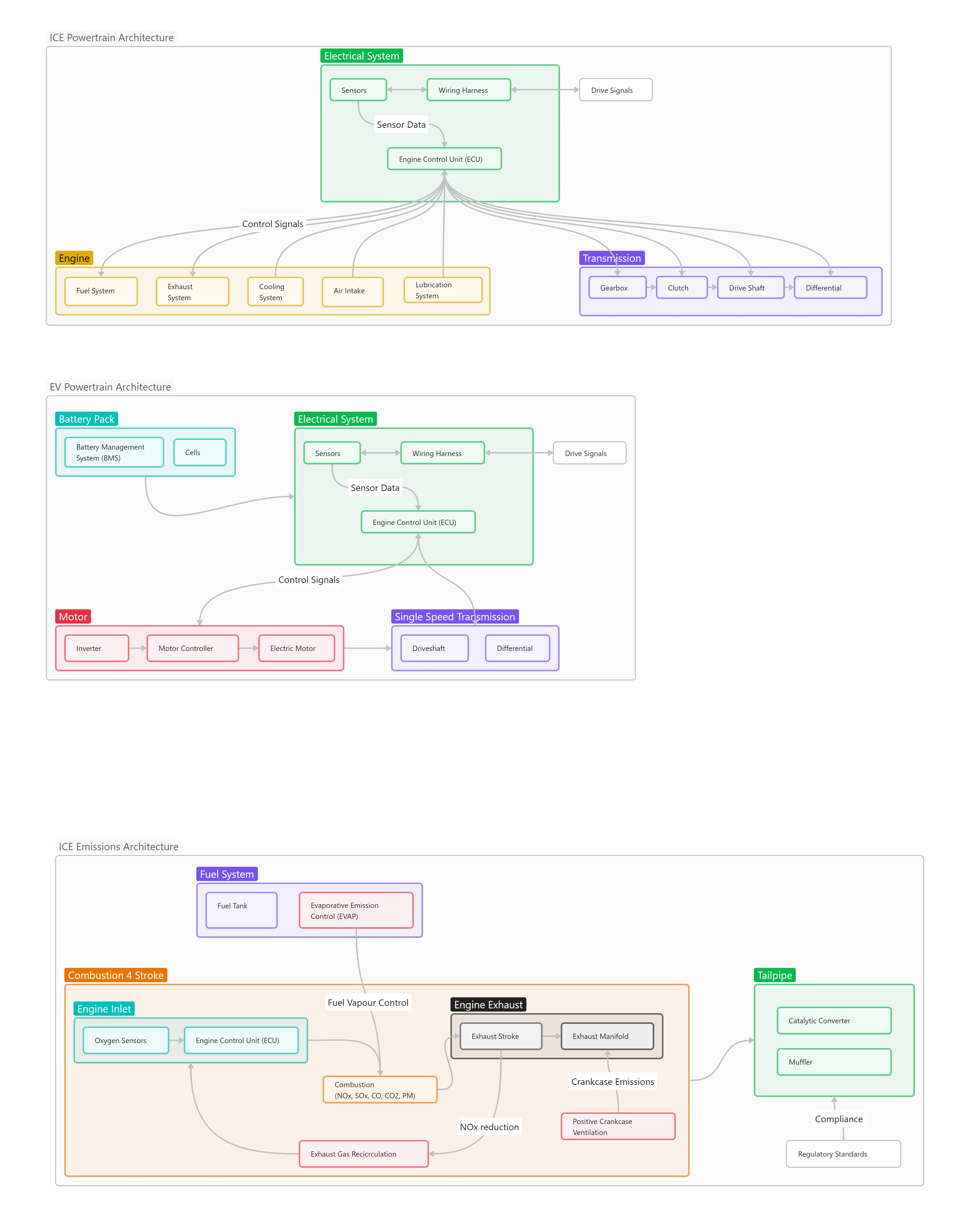
Power Flow Diagram
graph LR
    A[Battery] --> B[Power Delivery System] --> C[Motor]--> D[Transmission] --> E[Wheels]
    A --> F[12V Systems]
    E[Charging] --> A
Key Advantages of EV Architecture
Efficiency Comparison
pie title ICE Energy Efficiency
    "IC Engine Loss" : 50
    "Energy to Wheel" : 35
    "Transmission & Other Losses" : 15
pie title EV Energy Efficiency
"EV Motor Loss" : 5
"Energy to Wheel" : 80
"Transmission & Other Losses" : 15System Benefits
- Efficiency: Electric drivetrain is 3-4x more efficient than ICE
- Simplicity: Fewer moving parts than conventional vehicles
- Controllability: Precise electronic control of all systems
- Integration potential: Systems can be optimized together
- Scalability: Components can be sized for different vehicle classes
System Boundaries
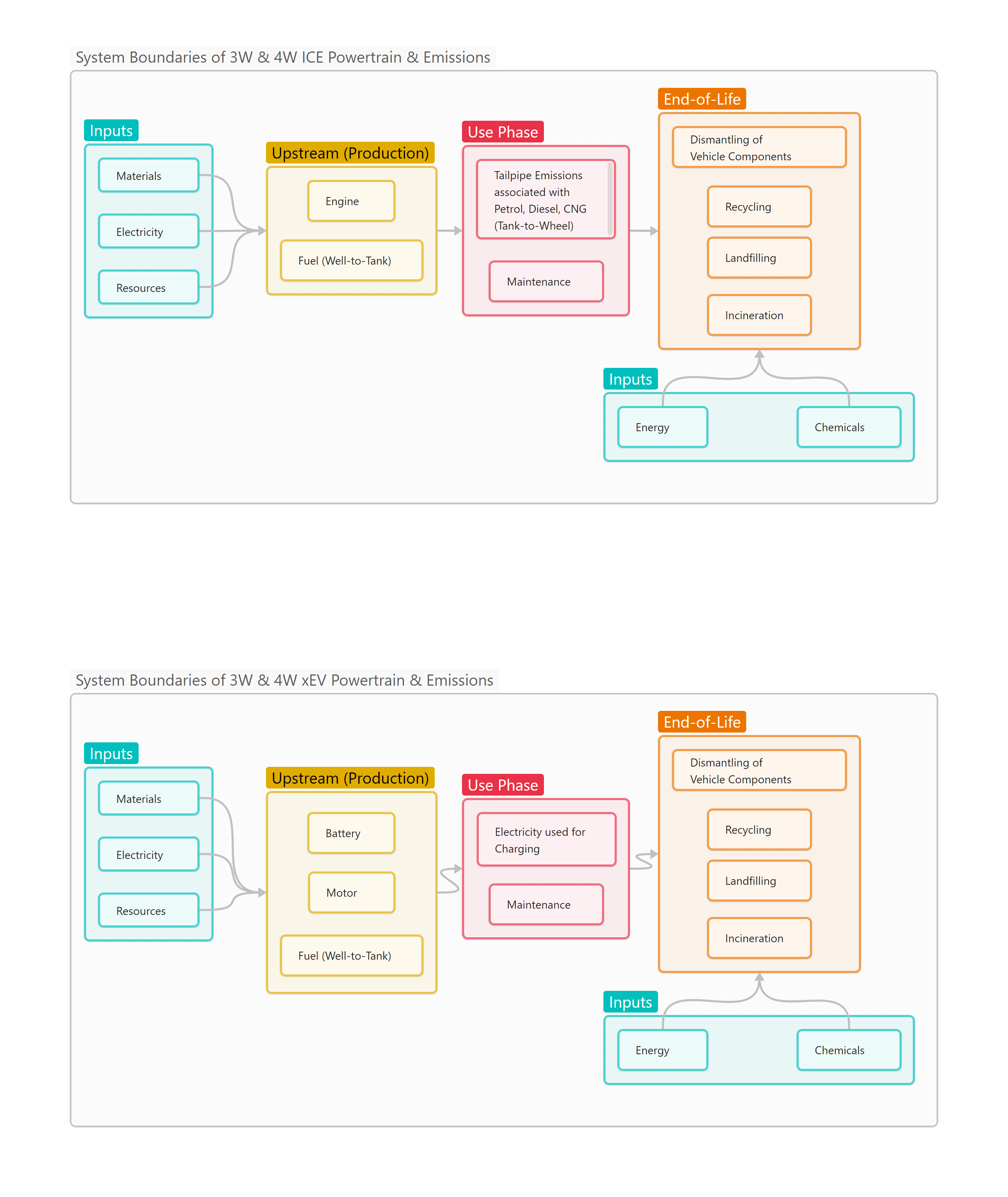
Difference Between ICE (Internal Combustion Engine) and EV (Electric Vehicle):
| Feature | ICE | EV |
|---|---|---|
| Energy Source | Fuel (Petrol/Diesel) | Battery (Electricity) |
| Efficiency | ~25-30% | ~80-90% |
| Emissions | High (CO₂, NOx) | Zero tailpipe emissions |
| Maintenance | High (engine, oil changes) | Low (fewer moving parts) |
| Noise | Loud | Silent operation |
| Performance | Gradual acceleration | Instant torque and acceleration |
Life Cycle Analysis (LCA)
- xEVs generally tend to have higher environmental costs associated at production and end-of-life phases
- ICE on the other hand has higher use phase emissions due to its reliance on fossil fuel for propulsion and the emissions the tailpipe will generate
- As use phase for average vehicles is pretty long at 15 years/ 1,00,000 (1L)kms, the total GHG emissions of ICE are higher when compared to other xEVs

Scan the QR Code or Click on the link to view an LCA calculator